



Different Types of Industrial Pressure Gauges
 Oct 14, 2026|
 View:10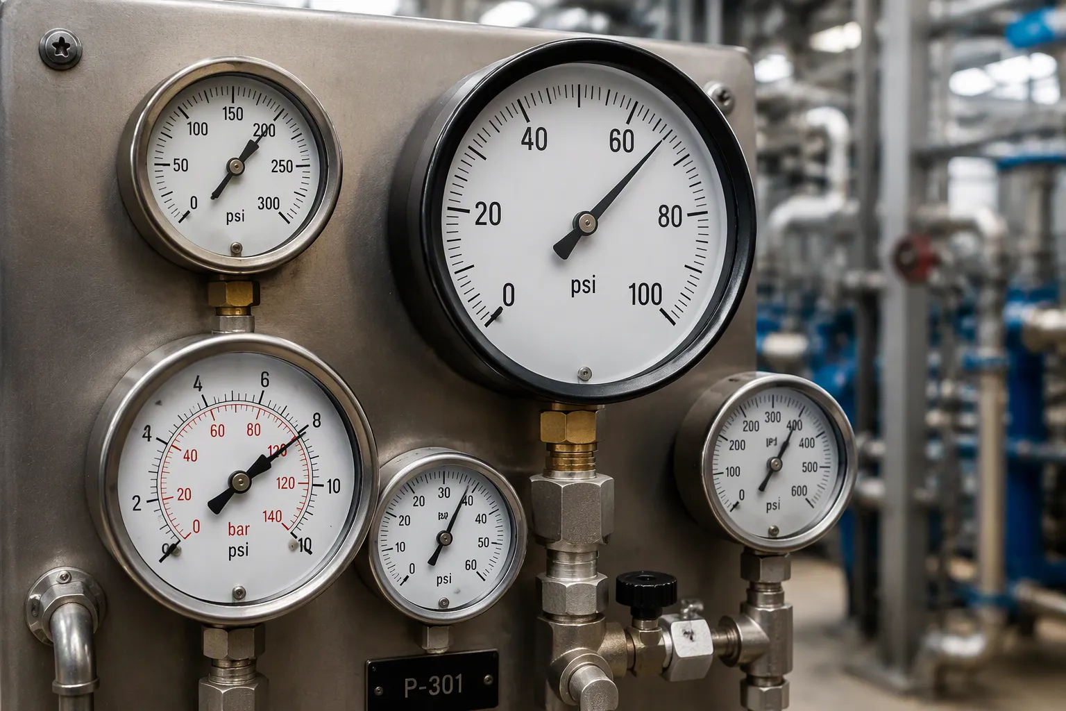
An industrial pressure gauge measures the pressure of gases or liquids in industrial systems. These instruments serve almost every sector, from marine and oil and gas to chemical, power, water, HVAC, and food processing. Industry estimates place the global pressure gauge market at roughly USD 1.5 billion in 2024, although published figures vary with how the market is defined.
Pressure gauges can be sorted in two ways. By sensing mechanism, the common designs are the Bourdon tube, bellows, diaphragm, and capsule — all mechanical. By the reference point they measure against, readings fall into four categories: gauge, absolute, differential, and vacuum or compound pressure. Around these mechanical designs sit specialized instruments such as the manometer, the piezometer, and digital or electronic gauges.
This guide offers a practical comparison of working principles, best-use applications, and selection factors for industrial pressure gauges. Proper selection supports safety, accuracy, and reliability.
Key Takeaways
Industrial pressure gauges measure pressure in gases or liquids. They help keep systems safe and accurate.
Common mechanical gauges include Bourdon tube, bellows, diaphragm, and capsule types. Each works best for specific pressure ranges.
Specialized gauges like absolute, differential, and compound measure pressure relative to vacuum or other pressures. They serve unique applications.
Selecting the right gauge involves checking pressure range, accuracy, media compatibility, environment, and connection type.
Regular calibration and a clear replacement threshold keep readings trustworthy. Accuracy class, temperature, and safety features all shape the final choice.
Industrial Pressure Gauge Types at a Glance
The table below compares the main gauge types side by side. Use it as a quick map, then read the sections that follow for the detail behind each row.
Gauge Type | How It Works | Typical Range | Best-Fit Applications |
|---|---|---|---|
Bourdon tube | A curved tube straightens under pressure and drives a pointer | Vacuum to about 1,600 bar | Process, steam, hydraulic, and marine systems |
Bellows | A sealed, accordion-like chamber expands or contracts | Low to moderate pressure | Low-pressure duties where accuracy matters more than size |
Diaphragm | A flexible membrane deflects under pressure | About 10 inH₂O to 300 psi | Low pressure, viscous or corrosive media |
Capsule | Two diaphragms joined at the edges form a capsule | Very low pressure | Low pressure with corrosive or clogging media |
Absolute | Measured against a sealed reference vacuum | Depends on the sensing element | Vacuum work where altitude and weather must not matter |
Differential | Compares two pressures directly | Depends on the sensing element | Filter blockage and pump performance monitoring |
Compound | Shows positive pressure and vacuum on one dial | A range spanning zero | Refrigeration, HVAC/R, and lines that prime under vacuum |
Manometer | A liquid column shows the pressure difference | Very low (mmH₂O) | Laboratory and low-pressure test work |
Piezometer | A standpipe or sealed probe reads pore-water pressure | Low (hydrostatic) | Groundwater monitoring and dam or slope safety |
Digital / electronic | A strain gauge or piezoelectric sensor outputs a signal | Wide, element dependent | Remote monitoring, data logging, and control systems |
Pressure Measurement Basics and Categories
How Industrial Pressure Gauges Work
Pressure is force applied over a surface area. When a gas or liquid pushes against a surface, the amount of force divided by the area gives the pressure reading. Industrial pressure gauges express this value in several units. Pascal (Pa) is the SI unit, defined as one Newton per square meter. Bar equals 100,000 Pascals. Psi, or pounds per square inch, is common in the United States for hydraulic and pneumatic systems.
Unit | Bar | Pa | kPa | psi |
|---|---|---|---|---|
Bar | 1 | ×100,000 | ×100 | ×14.50 |
Pa | ÷100,000 | 1 | ÷1,000 | ÷6,894.7 |
kPa | ÷100 | ×1,000 | 1 | ÷6.89 |
psi | ÷14.50 | ×6,894.7 | ×6.89 | 1 |
Read the table as a direction: to convert from the row unit to the column unit, apply the listed factor. For example, a reading of 4 bar becomes 4 × 14.50 = 58 psi.
Two measurement principles dominate. Hydrostatic gauges compare pressure to the force at the base of a fluid column. Mechanical gauges use a metallic sensing element that flexes elastically under pressure. A Bourdon tube is a curved, C-shaped hollow component. Pressurized fluid enters the tube and forces its flattened cross-section to become more circular. This elastic deformation straightens the tube, and the movement drives a pointer across a calibrated dial.
Gauge, Absolute, Differential, and Vacuum Pressure
Gauge pressure measures relative to current atmospheric pressure. When a gauge reads 0 bar(g), the system pressure equals the surrounding atmosphere. The relationship is Pg = Pabs − Patm, where Pg is gauge pressure, Pabs is absolute pressure, and Patm is atmospheric pressure. For example, if absolute pressure is 3 bar(a) and atmospheric pressure is 1 bar, the gauge pressure is 2 bar(g).
Absolute gauges reference a full vacuum instead. Differential gauges compare two pressures, which helps monitor filter blockages and pump performance. Compound gauges measure both positive pressure and vacuum. Vacuum pressure falls below atmospheric pressure. These categories guide the selection of industrial pressure gauges for specific tasks.
Mechanical Pressure Gauge Designs
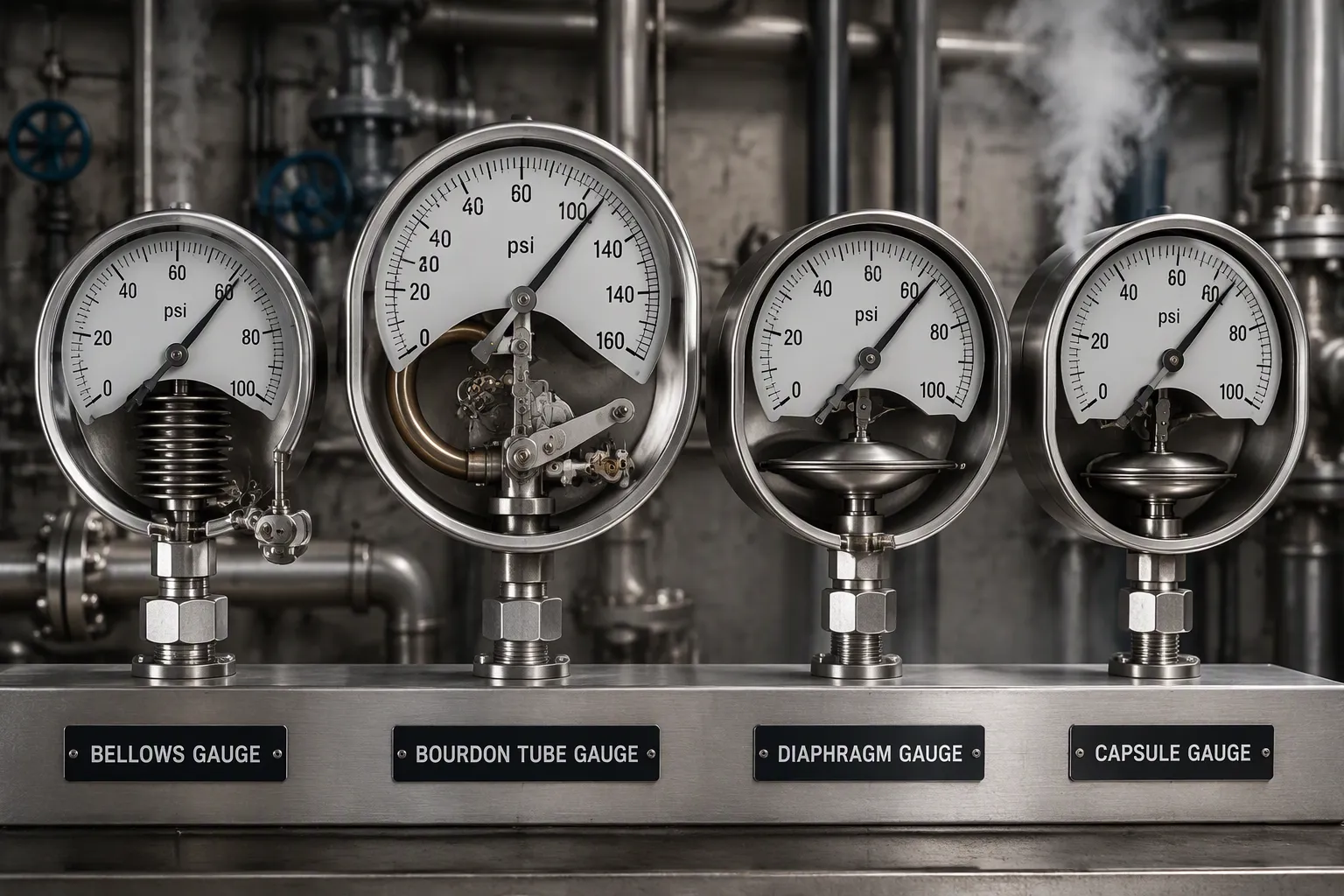
Mechanical pressure gauges remain the backbone of industrial measurement. These instruments rely on elastic elements that deform under pressure. The deformation drives a pointer across a dial. No external power is required. This simplicity explains their lasting presence in plants, ships, and utility systems.
Bourdon Tube and Bellows Gauges
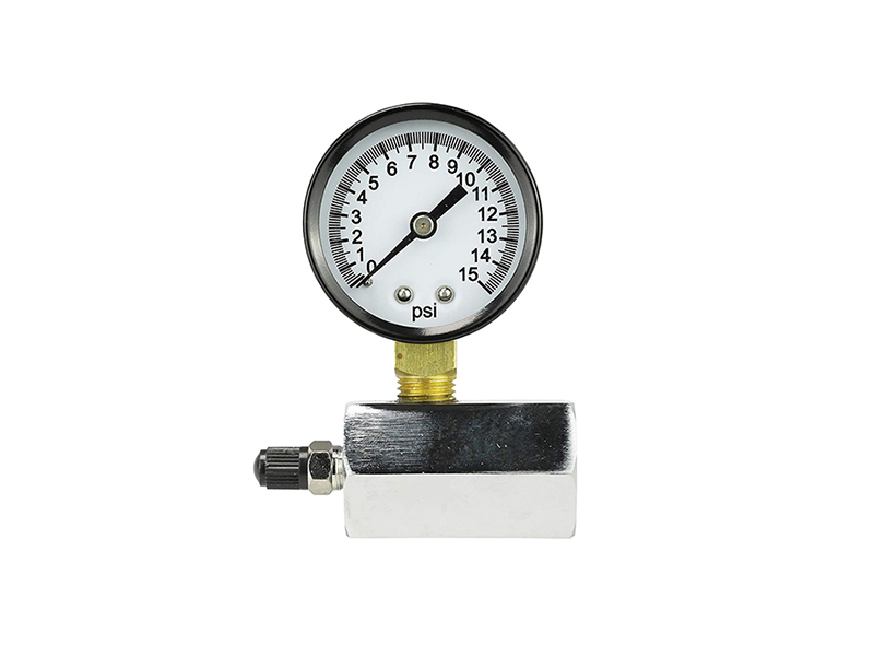
The Bourdon tube is the most common sensing element for medium to high pressure. A curved, hollow tube with a flattened cross-section straightens as pressurized fluid enters it. The tip of the tube moves, and a linkage amplifies that motion to rotate the pointer. Bourdon tube pressure gauges are suitable for medium to high pressure applications. Different variants extend the range further.
Bourdon tube variant | Typical pressure range | Where it fits |
|---|---|---|
C-type | Up to about 60 bar (≈870 psi) | The everyday element for general industrial service |
Spiral | About 60 bar to 1,000 bar | Medium to high pressure, more travel than a C-type |
Helical | Above 1,000 bar, commonly to about 1,600 bar (≈20,000 psi) | The highest pressure ranges, such as hydraulic test benches |
The C-type is the workhorse. Spiral and helical elements are selected as pressure rises, because a longer tube gives more pointer travel and better resolution at high pressure. Exact limits vary by manufacturer and material, so confirm the span against the supplier datasheet. For high-pressure hydraulic duties, a dedicated high-pressure gauge with a reinforced case is the safer choice.
Bellows gauges serve a different niche. A bellows is a sealed, accordion-like metal chamber. Pressure expands or contracts the bellows along its axis. The movement is larger than a Bourdon tube produces at the same pressure. This larger motion allows bellows gauges to offer high accuracy at moderate low pressure. They suit applications where precise readings matter more than compact size.
Diaphragm and Capsule Gauges
Diaphragm gauges use a thin, flexible membrane as the sensing element. Pressure pushes against the diaphragm, and the deflection is transmitted to the pointer. These gauges are ideal for low pressures. Typical low-pressure diaphragm gauges cover vacuum, compound, and positive pressure from about 10 inH₂O up to roughly 300 psi, while capsule-style designs can read as low as 0–20 inH₂O. These ranges show the low-pressure focus of diaphragm designs.
Capsule gauges take a related approach. Two diaphragms are joined at their edges to form a capsule. Pressure inside the capsule causes it to expand. The capsule moves a linkage and the pointer. Capsule gauges handle corrosive or clogging media when made with appropriate materials. A stainless steel capsule or a protective coating resists chemical attack. This makes capsule gauges a practical choice for viscous fluids and aggressive chemicals at low pressure.
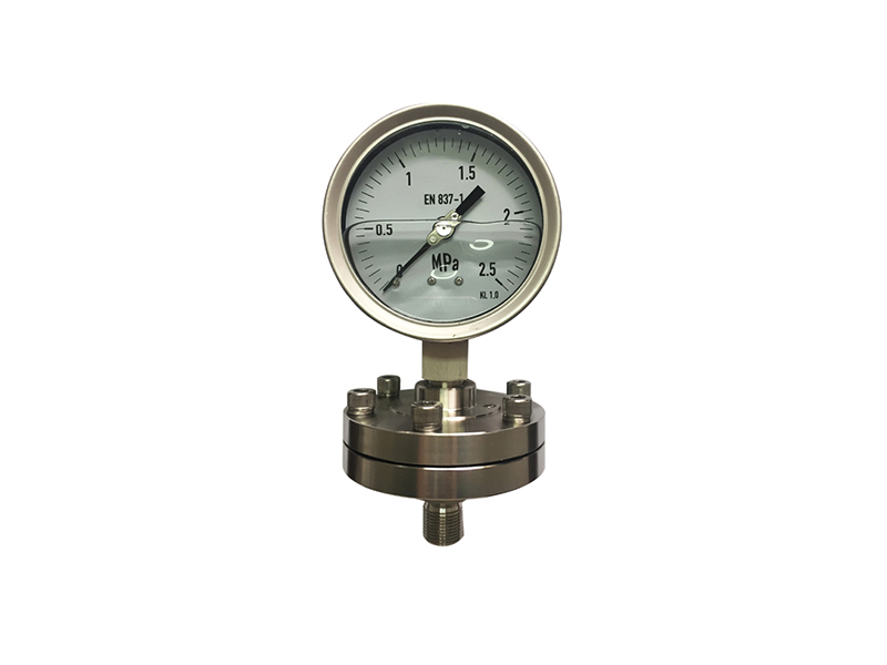
When the process fluid is too aggressive, hot, or viscous for the gauge itself, a diaphragm seal (also called a chemical seal) solves the problem. A flexible diaphragm isolates the gauge from the media and transmits pressure through a fill fluid. The wetted parts can then be matched to the chemistry — PTFE, Hastelloy®, or titanium, for example — while the gauge movement stays protected. Sealed assemblies are the standard choice for aggressive chemicals, slurries, and hygienic food or pharmaceutical lines.
Safety and Overpressure Features
Mechanical designs share common failure modes. A blocked orifice can freeze the pointer. Temperature cycling may fog the window. Zero drift often follows mechanical shock or process pulsation. Liquid-filled cases and external snubbers reduce these risks. Regular calibration every 6 to 12 months remains the most critical maintenance practice, and a gauge that consistently fails calibration or can no longer be adjusted within its accuracy class should be replaced. Standards such as EN 837-1, ASME B40.100, and GB/T 1226-2017 provide service criteria for industrial pressure gauges.
Safety is a design feature, not an afterthought. For steam, oxygen, or high-pressure service, choose a solid-front case with a blow-out back (EN 837-1 type S3). If the element fails, the energy is vented through the rear wall instead of toward the operator. A laminated safety glass window adds further protection. Where pressure surges are frequent, fit a snubber or restrictor screw to damp the pulses before they reach the movement. These features matter most on marine, offshore, and process lines, where a gauge failure can injure personnel as well as stop production.
Specialized and Electronic Pressure Gauges
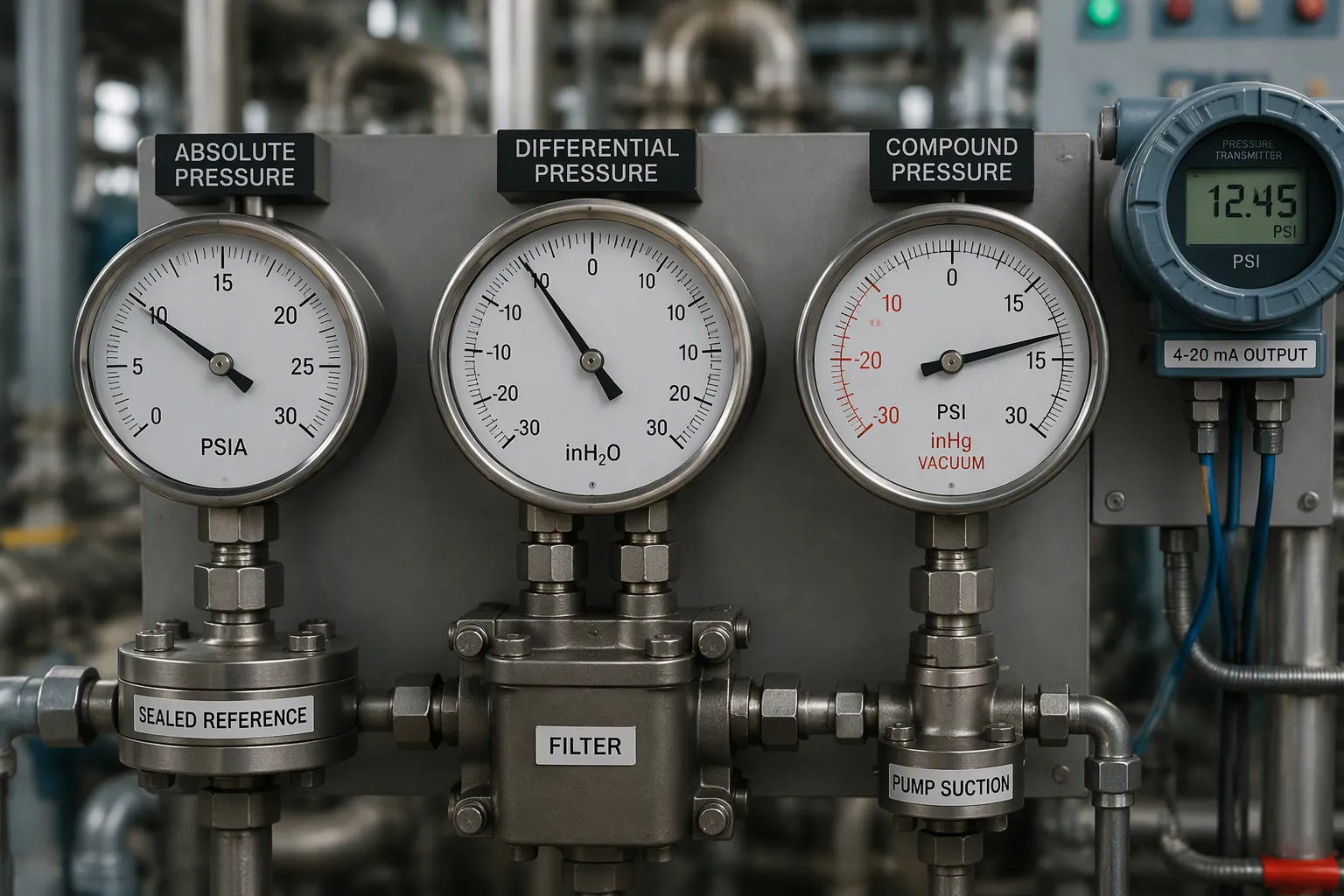
Specialized designs extend beyond common mechanical types. They address specific reference points and measurement conditions. Electronic versions convert pressure into electrical signals for remote reading and control. They handle tasks standard gauges cannot cover. They also handle vacuum, differential, and dynamic duties.
Absolute, Differential, and Compound Types
Absolute pressure gauges measure pressure relative to a perfect vacuum. That vacuum represents absolute zero pressure, where air is completely absent. This reference is fixed and unaffected by weather or altitude. Absolute pressure cannot be negative because zero is the floor. A full vacuum reads 0 PSIA. Average sea-level barometric pressure reads about 14.7 PSIA. Mechanical gauges usually calibrate at atmospheric pressure. Manufacturers calibrate at that pressure for many industrial uses, then offset the pointer upward by about 14.7 psi at zero. This method is acceptable for many industrial pressure gauges. It is not a true absolute design. True absolute mechanical gauges use isolated, sealed reference chambers. They cost more and appear less frequently in plants. Absolute references provide more accurate readings at vacuum levels because atmospheric pressure varies with weather and altitude.
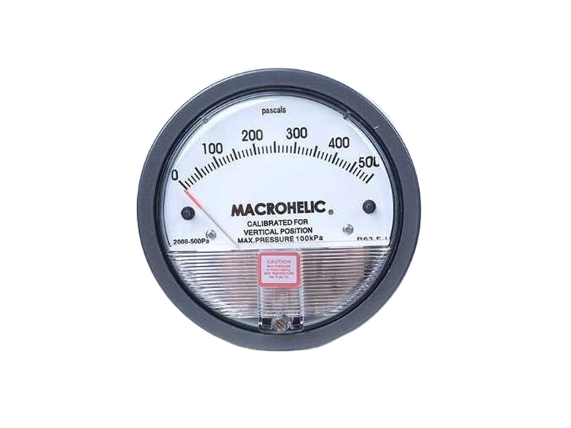
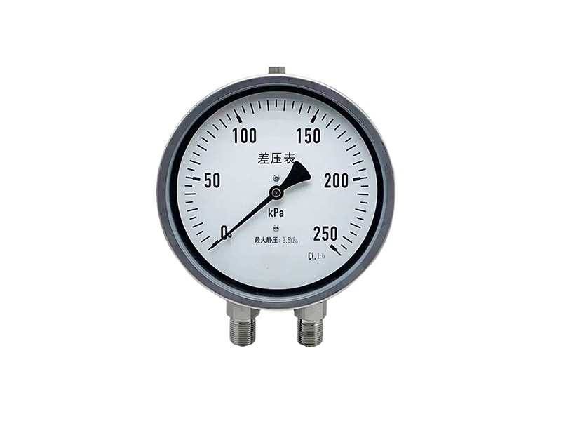
Differential pressure gauges compare two separate pressures. The gauges display the difference between the two sources. They monitor filter blockages, flow across orifices, and pump performance. A common application is checking the pressure drop across a filter. When the difference rises beyond a set point, the filter needs cleaning or replacement.
Compound pressure gauges measure both positive pressure and vacuum on one dial. These instruments serve applications crossing between vacuum and positive pressure. Common uses include:
Pump suction and discharge transitions
Vessel processing
Autoclave and sterilization cycles
Refrigeration service
HVAC/R systems
Industrial compressors
Water pumps
Lines that see vacuum during priming and positive pressure during normal operation
Laboratory and packaging systems also rely on compound gauges for similar transitions.
Manometer, Piezometer, and Digital Designs
Manometers measure pressure with a liquid column. A U-tube manometer shows pressure difference as a fluid height change. These tools suit low-pressure and laboratory work. Typical U-tube models cover ranges from 100-0-100 mmH₂O up to 1500-0-1500 mmH₂O, in steps such as 150-0-150, 200-0-200, 250-0-250, 400-0-400, 500-0-500, 600-0-600, 750-0-750, 1000-0-1000, and 1250-0-1250 mmH₂O. Some manometers extend to 3000-0-3000 mmH₂O for special low-pressure service.
Piezometers measure hydrostatic pressure in water or soil. A piezometer is a standpipe or sealed probe. It reads the pressure of pore water. Geotechnical engineers use them to monitor groundwater levels and dam stability. These tools remain essential for construction safety.
Digital pressure gauges use electronic sensing elements. Many digital models rely on strain gauge or piezoelectric technologies. A strain gauge element bends with pressure and changes its electrical resistance. That change becomes a readable pressure value. A piezoelectric sensor works through a clear sequence:
Pressure stresses the sensing element, producing an electrical charge proportional to the applied pressure.
The charge leaks away over time. The sensor suits dynamic pressure changes rather than static pressure.
A charge amplifier converts the charge into a usable voltage; some sensors include the amplifier internally.
High-temperature versions output raw charge for an external amplifier. Digital gauge displays provide high accuracy, data logging, and easy remote monitoring. These features make electronic designs valuable in modern control systems. Where a switch or alarm contact is needed on a mechanical dial, an electric contact pressure gauge offers a simple, power-free alternative. Liquid-filled mechanical gauges with stainless steel cases remain a proven choice among industrial pressure gauges for severe marine service.
How to Select Industrial Pressure Gauges
Selection is a process of elimination. Start with the pressure range and the required accuracy, then narrow by media, environment, connection, and display. The subsections below walk through each step in the order most engineers apply them.
Pressure Range, Accuracy, and Media Compatibility
Selecting the right gauge starts with the operating pressure range. EN 837-1 and ASME B40.100 set standard spans and the 75% range rule for normal operating pressure. This rule keeps the gauge reading in the middle portion of its scale, where accuracy is best. Accuracy class matters too. EN 837-1 defines classes 0.1, 0.25, 0.6, 1.0, 1.6, 2.5, and 4.0. Class 1.6 is the industrial default for general process, HVAC, and hydraulic work.
For standard industrial uses, an accuracy class of 1.6% is often sufficient, whereas laboratory settings may require 0.1% accuracy.
Media compatibility decides wetted part materials. For hydrogen sulfide and sulfur-containing media, choose H₂S-resistant gauges whose wetted materials comply with NACE MR0103 or MR0175. The two standards cover different industries: MR0175 / ISO 15156 applies to oil and gas production, while MR0103 applies to refinery and petrochemical service. Confirm which one your project follows. Favorable conditions with low H₂S and chloride levels suit 316 stainless steel or Alloy 20. Moderate conditions call for super duplex steels or Alloy 400 (Monel®). Extreme conditions with high H₂S, chlorides, acids, and high temperatures demand Hastelloy® C22/C276, Alloy 400, or titanium.
Environment, Connection, and Display Preferences
The operating environment shapes the gauge body and fill. Marine and seaport settings may require liquid-filled gauges with stainless steel cases and corrosion-resistant connections. Glycerine or silicone oil filling damps pointer flutter, improves reading stability, and protects internal parts from shock. These gauges suit hydraulic machinery, compressors, pumps, and other dynamic equipment. Outdoor installations need at least IP65 ingress protection under EN 60529.
Connection size follows gauge diameter. Smaller gauges commonly use 1/4 NPT, while 100 mm and 150 mm gauges use 1/2 NPT. North American industrial plants rely on both sizes. Display preference ranges from analog dials to digital readouts with data logging. For a general-purpose dial with dependable sealing, a standard liquid-fillable gauge with a bayonet ring is a common starting point.
Temperature Effects and Long-Term Reliability
Accuracy class is specified at a reference temperature, usually 20 °C. Away from that reference, the reading drifts. Manufacturers commonly quote an additional temperature error of about 0.04% of span per °C for a Class 1.6 gauge, so a 40 °C swing can shift the indication by more than the class itself. Where the process or ambient temperature varies widely, choose a gauge with temperature compensation, or keep the gauge cooler with a siphon or a capillary. On steam service, a pigtail siphon both cools the incoming media and protects the element.
Calibration, long-term reliability, and supplier reputation round out the decision. A specialist manufacturer such as Changzhou KB Instruments & Meter Co., Ltd. serves marine and industrial markets with pressure gauges and thermometers. Careful selection of industrial pressure gauges improves safety, accuracy, and equipment longevity.
Mechanical types (Bourdon tube, bellows, diaphragm, and capsule) remain dependable for most duties. Specialized absolute, differential, and compound designs fit specific reference needs. Manometers, piezometers, and digital gauges cover liquid-column and electronic measurement. Selection depends on range, accuracy, media compatibility, environment, connection, and display. First, identify whether you need gauge, absolute, differential, or vacuum/compound pressure.
Why Correct Selection Improves Safety
A gauge is often the only window into a pressurized system. When it is chosen well, it protects both equipment and people.
Safety Benefit | Explanation |
|---|---|
Early hazard warning | Accurate readings alert operators before incidents occur. |
Over-pressurization prevention | Correct data avoids catastrophic leaks and equipment failure. |
Personnel protection | Solid-front cases and real-time pressure keep systems within safe limits. |
Need help matching a gauge to a specific line? Contact Changzhou KB Instruments & Meter Co., Ltd. for product data, OEM options, and selection support.
FAQ
How often should industrial pressure gauges be calibrated?
The right interval depends on how critical the reading is and how harsh the service is. A practical starting point:
Service | Suggested interval |
|---|---|
General industrial, clean media | 12 months |
Process or utility lines with moderate pulsation | 6–12 months |
Critical safety or custody service | 6 months |
Marine, offshore, or heavy vibration | 3–6 months |
Newly installed gauges | Recheck after the first 6 months |
A gauge should be replaced when it can no longer be adjusted to read within its accuracy class. For a Class 1.6 gauge, that means the error can no longer be brought back inside ±1.6% of full scale. Many plants also set an earlier internal trigger — for example, a drift of more than 1.0% of full scale between calibrations — as a warning sign, even while the gauge still meets its published class.
What is the 75% range rule for pressure gauge selection?
The rule comes from EN 837-1 and ASME B40.100. A gauge is most accurate in the middle of its scale, so the normal working pressure should sit at roughly two-thirds to three-quarters of the full-scale value — in practice, the dial is sized so the typical reading lands near 75% of the maximum. A line that normally runs at 6 bar would therefore call for a 0–10 bar gauge rather than a 0–6 bar or 0–25 bar one. This keeps the pointer in its linear region, extends service life, and leaves headroom for pressure spikes. If the line also drops into vacuum during priming, choose a compound range instead.
When should I choose a liquid-filled pressure gauge?
Choose liquid filling when vibration or pressure pulsation would otherwise make the pointer flutter and wear the movement. Glycerine and silicone oil are the common fills, and silicone tolerates higher temperatures. Liquid filling also protects internal parts from shock.
There are cases where liquid filling is not the best choice. Very low-pressure diaphragm and capsule gauges often perform better dry, because the fill can add a small temperature-dependent offset. Hygienic food and pharmaceutical lines may avoid fills that cannot be cleaned in place. And in cold outdoor service, glycerine thickens and can slow the response. Match the fill fluid to the expected temperature range before specifying it.
What accuracy class works for most industrial applications?
Class 1.6 is the everyday default for general process, HVAC, and hydraulic service. It is accurate enough for most monitoring duties at a reasonable cost. Higher classes cost more: Class 1.0 and 0.6 suit test benches and quality-critical processes, while Class 0.25 or 0.1 belongs in calibration laboratories. EN 837-1 defines the full set — 0.1, 0.25, 0.6, 1.0, 1.6, 2.5, and 4.0 — where the number is the maximum error as a percentage of full scale. Note that class describes accuracy, not resolution: a digital gauge may display many digits yet still be a Class 1.0 device.
Which wetted materials resist hydrogen sulfide media?
Hydrogen sulfide and other sulfur compounds attack many common alloys, so the wetted parts must be chosen for the service. Two standards are usually referenced, and they cover different industries: NACE MR0175 / ISO 15156 applies to oil and gas production, while NACE MR0103 applies to refinery and petrochemical service. A simple selection ladder helps:
Low H₂S and chloride levels, favorable conditions — 316 stainless steel or Alloy 20
Moderate conditions — super duplex stainless steel or Alloy 400 (Monel®)
High H₂S, chlorides, acids, and high temperatures — Hastelloy® C22/C276, Alloy 400, or titanium
Always confirm the exact material against the process conditions and the applicable standard before ordering.
I want to comment
Recent News
1.Who Are the Best Pressure Gauge Manufacturers and Pressure Gauges Suppliers in 2026?
2026-09-172.Are Oil-Filled Pressure Gauges Better? A Complete 2026 Comparison Guide for Industrial Buyers
2026-05-073.Dry vs. Liquid-Filled Pressure Gauges: How to Choose for Marine Use
2026-09-244.A Closer Look at the Four Main Types of Pressure Gauges
2025-08-185.Understanding Digital Pressure Gauges
2025-11-18




View More(Total0)Comment lists