



Pressure Gauge Bouncing or Drifting? 5 Causes and Calibration Guide
 Sep 28, 2026|
 View:14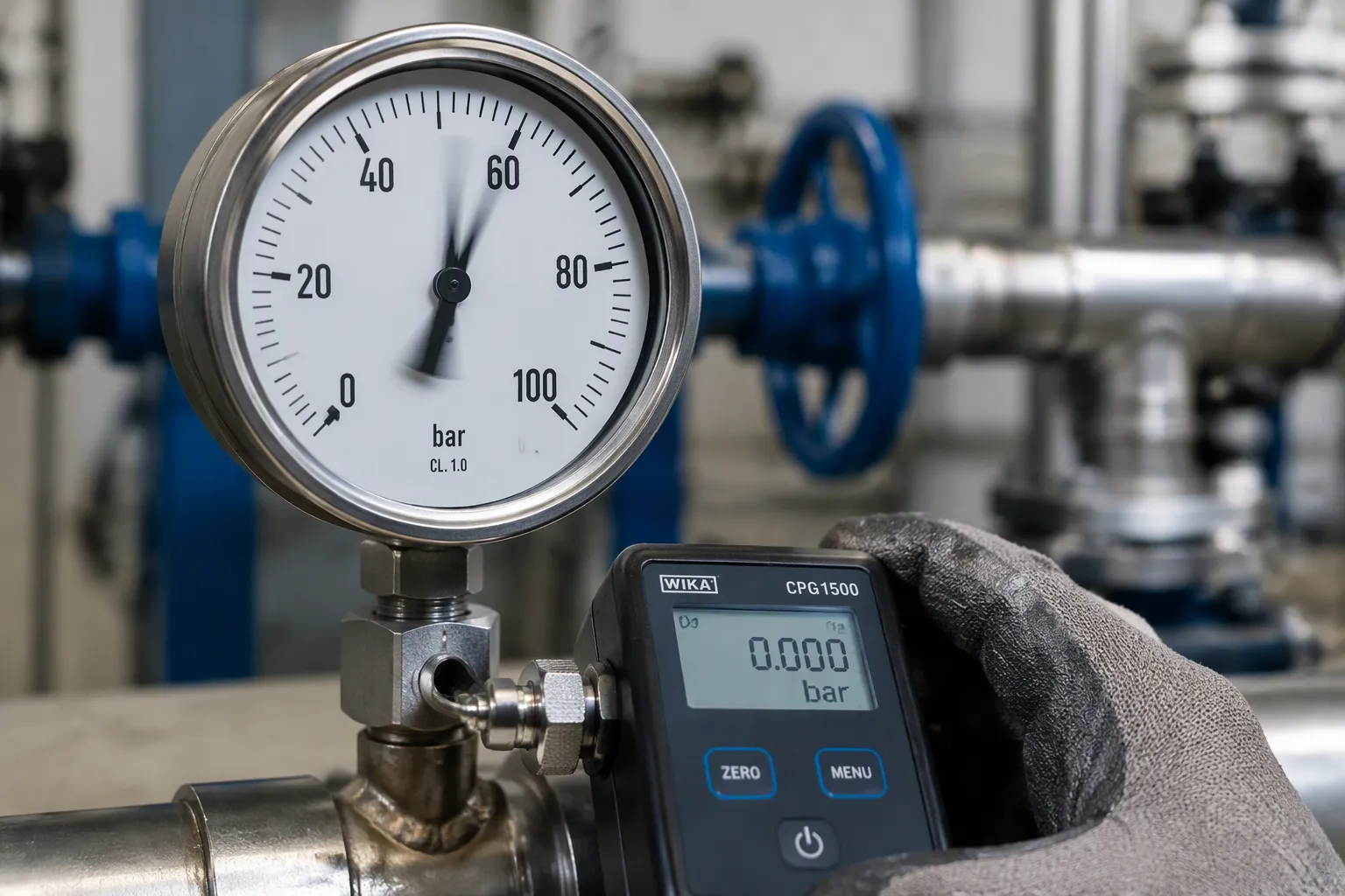
A bouncing or drifting pressure gauge needle is a critical warning sign. Needle bouncing (flutter) is typically caused by system pulsation, vibration, or trapped air, requiring dampening solutions like liquid-filled gauges or snubbers. Reading drift, conversely, indicates calibration loss, Bourdon tube fatigue, or temperature overload, necessitating field calibration or replacement. With over 15 years of manufacturing expertise, Changzhou KB Instruments provides this definitive troubleshooting and field calibration guide to help maintenance teams diagnose root causes accurately and restore measurement reliability across industrial and marine (IMPA) applications.
Key Takeaways
Rhythmic bouncing from pump pulsation or vibration requires a snubber or liquid-filled gauge to smooth the reading.
Erratic bouncing with sticking or jumping points to worn internal parts. Replace the gauge instead of repairing it.
Trapped air bubbles in liquid-filled gauges cause bouncing at certain angles. Bleed the air through the fill plug to restore damping.
Wrong gauge range or type causes bouncing. Use a gauge with normal pressure in the middle fifty percent of its scale.
Field calibration requires zero and span adjustment plus a five-point test. Use a known reference standard and calibrate at operating temperature.
Symptom vs. Root Cause Matrix
Observed Symptom | Primary Root Cause | Immediate Field Fix |
|---|---|---|
Rhythmic Bouncing / Flutter | Pump pulsation / Mechanical vibration | Install snubber or upgrade to liquid-filled gauge |
Erratic Jumping / Sticking | Worn linkage / Corroded movement | Replace gauge immediately |
Angle-Dependent Bounce | Trapped air in liquid-filled case | Bleed air via top fill plug |
Reading Drift (Zero/Span Shift) | Overpressure fatigue / Temperature shift | Perform 5-point field calibration |
Sluggish / Lagging Response | Clogged snubber / Blocked port | Clean or replace snubber |
Cause 1: Pulsation and Vibration
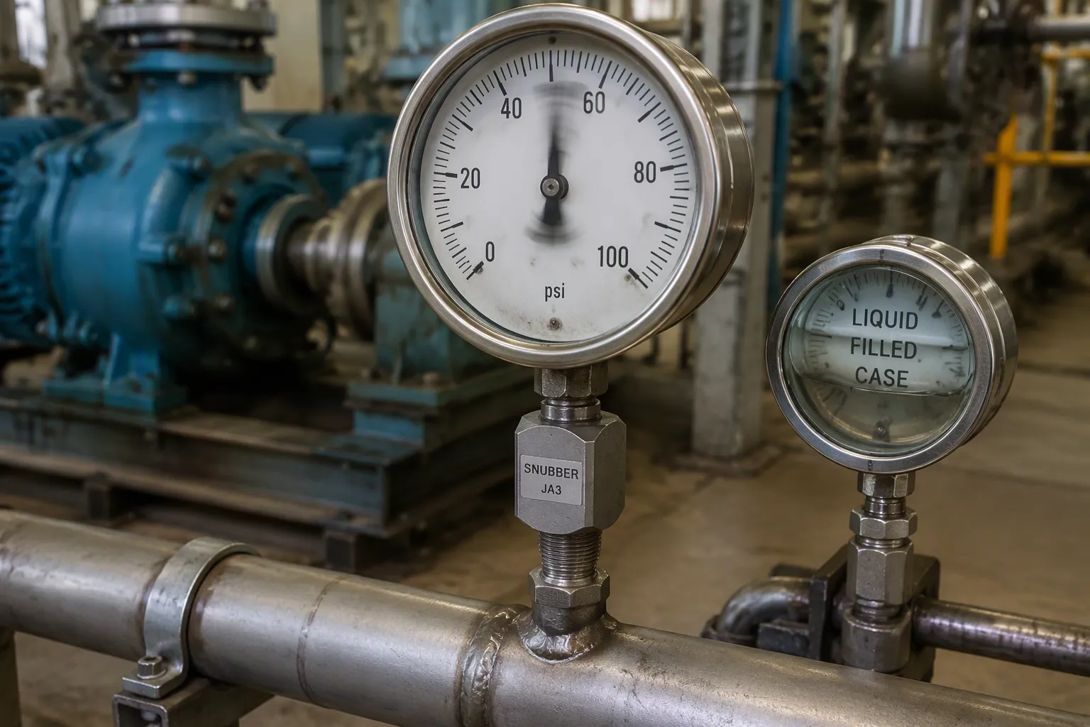
A pressure gauge needle bouncing usually originates from one of three root sources. Mechanical vibration of the gauge case is one source. System pulsation from a pump or compressor is a second. A damaged internal mechanism is the third. This cause covers the first two sources. The combination of vibration and pulsation from rotating equipment produces the most common needle stability problems in industrial settings. These two factors often appear together.
Symptoms of Pressure Gauge Needle Jumping
The primary symptom involves a steady, rhythmic oscillation. The pressure gauge needle moves in time with each pump stroke or compressor cycle. An operator can feel vibration on the pipe or mounting bracket. The reading stabilizes when the line isolates the gauge from the process. This isolation test provides a rapid diagnostic method. A jumping pressure gauge needle that follows mechanical cycles points to pulsation or vibration rather than internal wear. The bouncing pattern repeats at predictable intervals. The gauge may also show a vibrating needle that appears to blur rather than jump. These symptoms confirm that external mechanical forces cause the problem.
Field Fixes: Snubbers and Liquid-Filled Gauges
Two primary field fixes address this condition. The first involves installing a snubber in the pressure line. A snubber sits between the gauge and the pressure source. It smooths out pressure pulsation and pressure spikes before they reach the sensor. Snubbers prevent needle flutter and protect internal components. They provide more accurate and stable readings. The second fix involves switching to a liquid filled gauge. Glycerin or silicone oil inside the case dampens pointer movement. This upgrade often turns an unreadable gauge into a dependable indicator. However, a liquid filled gauge case is not a cure-all. Extreme pulsation may still require a snubber. Severe vibration may require remote mounting or isolators.
A liquid filled gauge case is not a cure-all. Extreme pulsation may still require a snubber, restrictor, or pulsation dampener. Severe vibration may require remote mounting or isolators. Still, liquid fill is often the first upgrade that turns an unreadable gauge into a dependable indicator.
Different snubber types suit different pulsation conditions. Porous snubbers work for mild pulsations. Orifice snubbers handle high-pressure spikes. Piston snubbers address extreme pulsations in hydraulic systems. For vibration problems, mount the gauge with vibration dampeners. A remote capillary mount also isolates the gauge from mechanical vibrations. On-site verification helps confirm the fix. Tee in a second gauge to compare readings. This step confirms whether the correction worked. Standard pressure gauges in vibrating services should always use liquid filling, such as the robust KB Instruments PG-03C Oil Filled Gauges. The fill fluid absorbs energy and stops the needle from bouncing. These pressure gauges last longer and read more accurately with proper damping. A snubber remains a wear part. Inspect it at each calibration interval.
Cause 2: Worn Internals and Reading Drift
Internal wear produces a different bounce pattern than pulsation or vibration. Four main faults cause this problem: loose linkage, bent sector gears, corroded movement, and overpressure damage. Each fault interferes with the mechanical linkage that translates pressure into needle movement. The result is a pressure gauge needle that no longer tracks pressure smoothly, often manifesting as reading drift.
Symptoms: Erratic Movement and Reading Drift
A worn gauge behaves unpredictably. The pressure gauge needle sticks in one position, then jumps suddenly to a new reading. The bounce pattern appears random rather than rhythmic. This randomness separates internal wear from pulsation problems. A damaged gauge may also rest above zero with no pressure applied (Zero Drift). The needle fails to return to the zero mark after pressure releases. Reading drift after an overpressure event points to bent or stretched internal parts, specifically Bourdon tube fatigue. These symptoms confirm that the movement assembly requires attention or replacement.
Field Fixes and When to Replace
A loose linkage screw is sometimes accessible behind the lens. Tightening it may restore smooth operation. Most other internal faults require replacement. Bent sector gears, corroded movements, and overpressure damage are usually permanent. A gauge that will not hold calibration after two attempts should be replaced. Commercial pressure gauges are relatively inexpensive. A new gauge often costs less than sourcing parts and paying repair labor. New gauges also arrive with factory warranties and calibration traceability. Replacement minimizes downtime because installation is faster than shipping a unit out for repair.
The table below summarizes replacement guidance by gauge type.
Gauge Type | Repair vs. Replace Recommendation |
|---|---|
Commercial Pressure Gauges | Replacement is always the most economical path. |
Industrial Pressure Gauges | Complex internal parts are difficult to restore to factory calibration; replacing ensures long-term reliability. |
Repairing electronics is impractical and may introduce performance errors. | |
Differential Pressure Gauges | Attempted repairs can disrupt accuracy and compromise system efficiency. |
Test Gauges | A repaired test gauge may no longer meet the stringent accuracy class required. |
High Purity and Sanitary Gauges | Any tampering or repair compromises sanitary certification; only validated, factory-sealed replacements are acceptable. |
Gauges with physical damage or repeated calibration failures should be replaced. Replacement removes a gauge that can no longer be trusted or repaired.
To confirm a diagnosis, tee in a second gauge at the same port. Compare both readings under identical pressure. A large discrepancy confirms internal damage. This simple test prevents unnecessary replacement of a healthy gauge.
Cause 3: Trapped Air in Liquid-Filled Gauges
Liquid filling dampens needle movement by surrounding the internal mechanism with glycerin or silicone oil. The fluid absorbs vibration energy and stops the pointer from oscillating. A trapped air bubble defeats this damping entirely. The bubble compresses and expands as pressure changes, allowing the needle to bounce freely inside the case. This condition mimics the symptoms of pulsation or internal wear, which makes diagnosis tricky without a close visual inspection.
Symptoms and Quick Confirmation
A visible bubble behind the lens is the clearest confirmation. Tilt the gauge or view it from different angles to spot the air pocket. The pressure gauge needle bouncing often appears only at certain mounting angles. A gauge mounted horizontally may bounce while the same unit mounted vertically reads steady. This angle-dependent behavior separates trapped air from mechanical faults. Recent refilling or installation upside down also points to this cause. Air enters during service work or when the fill plug sits below the fluid level. A quick shake test helps confirm the diagnosis. Gentle agitation moves the bubble, and the needle behavior changes in response.
Field Fixes: Bleeding and Refilling
The repair procedure is straightforward. Isolate the gauge from the process and depressurize the line. Locate the fill plug or vent at the top of the case. Open it slowly to release trapped air. Top off the case with the correct fill fluid until the level reaches the fill line. Reseal the plug and recheck the gauge under pressure. The needle should now move smoothly without bouncing.
Fill fluid selection matters for long-term performance. Silicone oil maintains stable viscosity across a wide temperature range. Glycerin performs well in moderate conditions but thickens substantially in cold environments. Both fluids dampen vibration effectively when the case remains free of air. Choose the fluid that matches the expected operating temperature of your pressure gauges. Proper bleeding restores full damping and extends service life for any liquid filled gauge.
Cause 4: Wrong Gauge Selection or Range
A pressure gauge needle bouncing often traces back to an improper gauge selection for the application. Operating a gauge in the bottom or top ten percent of its rated range forces the internal mechanism to work outside its optimal zone. The linkage and sector gear experience excessive wear under these conditions. A dry gauge installed on a vibrating pump line will bounce continuously. Incorrect wetted materials can cause corrosion that seizes the movement. Each of these selection errors leads to instability and short service life.
Symptoms and Quick Confirmation
The most telling symptom involves the operating point on the dial. Normal process pressure sits below ten percent or above ninety percent of the full-scale range. A 1000 psi gauge reading a steady 50 psi process represents a gross range mismatch. A dry gauge on a reciprocating compressor line almost always bounces. The vibration from the machine travels directly into the case. No fill fluid exists, so no damping occurs. Wrong wetted materials cause visible corrosion or pitting on the connection threads. The needle may bounce erratically as corrosion products interfere with the movement. A quick comparison with properly selected pressure gauges confirms the diagnosis. Tee in a reference gauge that matches the service. If the reference reads steady while the suspect gauge bounces, selection error is the root cause.
Field Fixes: Reselecting the Gauge
The correction involves replacing the gauge with a properly specified unit. The normal operating pressure must fall in the middle fifty percent of the scale. Industry guidance places normal operating pressure between twenty-five and seventy-five percent of full scale.
Industry guidance commonly places normal operating pressure between 25% and 75% of full scale. Ashcroft’s pressure-gauge selection guidance, referencing ASME B40.100 and EN 837-1, recommends keeping the pointer in this middle portion of the dial.
A 150 psi gauge suits a process that runs at 80 psi. Match the gauge type to the service conditions. Use a liquid filled gauge for vibrating machinery. The fill fluid absorbs vibration energy and stops the needle from dancing. Use a process gauge for services with severe pressure pulsation. A process gauge has a heavier case and a more robust movement for handling system pulsation. The oil filled vs dry pressure gauge decision depends on the application. Vibration demands liquid fill. Dry gauges work only on steady systems without mechanical disturbance. Correct selection prevents most repeat bouncing problems. These pressure gauges operate reliably when matched to the application. A dry gauge offers no protection against pulsation. The use of improper pressure gauges in critical applications introduces unnecessary risk.
Cause 5: Clogged or Damaged Snubber
A snubber restricts flow to smooth pressure spikes before they reach the gauge mechanism. This small component sits in the pressure line and acts as a buffer against sudden changes. When the snubber clogs with debris or its orifice wears larger, it either blocks the signal entirely or stops damping altogether. A blocked snubber prevents pressure from reaching the gauge. A worn orifice allows pulsation to pass through unchecked. Both conditions produce unstable readings and erratic pointer behavior.
Symptoms and Quick Confirmation
A clogged snubber creates a distinctive response pattern. The pressure gauge needle moves slowly at first, then jumps suddenly to a new position. The pressure reading lags behind actual process changes. An operator may notice the gauge responds sluggishly to valve adjustments. Visual inspection of the snubber often reveals the root cause. Debris, corrosion products, or a visibly worn orifice confirm the diagnosis. Process fluid contamination accelerates snubber degradation. Systems with dirty fluids or reactive chemicals clog snubbers faster than clean hydraulic circuits. To confirm the diagnosis, tee in a second gauge at the same port without a snubber. Compare both readings under identical pressure. A large discrepancy between the two pressure gauges confirms snubber blockage or wear.
Field Fixes: Cleaning or Replacing the Snubber
The repair procedure requires careful attention to safety. Isolate the line and depressurize the system before any work begins. Never remove a snubber while the line is pressurized. High-pressure fluid can cause serious injury. Once isolated, remove the snubber from the gauge connection. Inspect the orifice for debris, corrosion, or wear. Clean the orifice with appropriate solvents and compressed air. Replace the snubber if the orifice shows visible wear or damage. A snubber is a wear part and should be inspected at each calibration interval. Regular inspection prevents unexpected failures and maintains accurate pressure gauges. Proper snubber maintenance extends the life of pressure gauges in pulsation-heavy services. Vibration and pulsation accelerate wear on all damping components. Routine replacement schedules reduce downtime and improve measurement reliability.
Field Calibration of Pressure Gauges: Step-by-Step

Safety, Tools, and Zero Adjustment
Safety procedure comes first. Confirm all pneumatic and hydraulic pressure gauges read zero on every circuit. Slowly open a downstream fitting or drain valve to verify no residual pressure exists. Never open a fitting without first confirming zero pressure. Attempt to operate machine controls to ensure all energy sources are isolated. For hydraulic and pneumatic systems, set valves to the closed position, lock them, and then bleed residual energy by slowly opening pressure relief valves. After bleeding, verify depressurization by checking gauges again.
ISO/IEC 17025 Clause | Requirement Related to Traceability |
|---|---|
Clause 6.4 (Equipment) | Measuring equipment must not introduce unacceptable uncertainty; calibration status must be maintained. |
Clause 7.6 (Evaluation of Measurement Uncertainty) | Laboratories must identify uncertainty contributions and evaluate them using appropriate methods. |
Clause 7.8 (Reporting of Results) | Calibration certificates must include measurement uncertainty, conditions, and traceability statement. |
Clause 6.2 (Personnel) | Staff must be competent in uncertainty evaluation, traceability, and reference standard limitations. |
Tools required include a known reference standard such as a deadweight tester or a calibrated master gauge. A deadweight tester offers the best accuracy. A master gauge system with a pump is more portable and easier to use in the field. For field applications, a high-precision master gauge like the KB Instruments PG-15 Precision Test Gauge (Class 0.4 or 0.25) offers excellent portability and traceability. Gather appropriate fittings, a small flathead screwdriver for the zero screw, and a wrench.
Zero adjustment starts the calibration of pressure gauges. With no pressure applied, check the needle position. A mechanical pressure gauge may stay within acceptable zero tolerance if the needle rests slightly above zero. If the needle shows this small offset, turn the mechanical zero screw until the needle aligns with zero. This zero screw appears on most analog gauges.
Span Adjustment and 5-Point Testing
Span adjustment follows zero verification. Apply full-scale pressure to the gauge. Adjust the span linkage or screw so the needle reads exactly full scale. Recheck zero after each span change because zero and span interact. Repeat the adjustment cycle until both points hold.
A 5-point test verifies overall accuracy. Test the gauge at 0%, 25%, 50%, 75%, and 100% of range in ascending order. Then test the same points in descending order from 100% down to 0%. Compare ascending and descending readings at each test point to quantify hysteresis. Verify linearity by confirming consistent accuracy across the entire span. Recognized procedures such as ASME B40.100 and EN 837-1 specify this minimum five-point method.
Application Category | Typical Accuracy Class | Examples |
|---|---|---|
Test gauges and standards | 0.25% or better (down to 0.10%) | Calibration laboratories, metrology, scientific research |
Critical processes | 0.5% or better | Pharmaceuticals, aerospace, nuclear power |
General industrial processes | 1.0% to 1.6% | Chemical processing, oil and gas, manufacturing, marine (IMPA) |
Gauges with lower accuracy classes are not recommended for calibration labs or highly critical measurements, where Class 0.6 or 0.25 is required.
Calibration should be traceable to national or international standards such as ISO/IEC 17025. Accreditation ensures every measurement connects to recognized metrology institutes. Defined measurement uncertainty, competent personnel, validated methods, and environmental controls all contribute to reliable results.
Temperature variation affects calibration accuracy. The Bourdon tube elastic modulus changes with temperature, altering tube deformation and causing zero shift. In liquid-filled gauges, fill fluid expansion increases internal pressure. Silicone fill performs better than glycerin across wider temperature ranges. Digital gauges experience sensor temperature drift without compensation algorithms. Perform calibration at the expected operating temperature where possible. Common calibration errors include zero error, span error, linearity error, hysteresis, and friction. A known-good gauge teed into the line helps confirm whether a suspect gauge needs adjustment. Pulsation from pumps often causes bounce in field gauges, so verify the pressure source is stable during calibration. Vibration can also distort readings, so isolate the gauge during testing.
Digital gauges may need software-based calibration instead of mechanical screws. Consult the manufacturer manual for digital unit procedures.
KB Instruments (Changzhou KB Instruments & Meter Co., Ltd.) manufactures liquid-fillable gauges, precision test gauges, and oil-filled gauges with record pointers suited to bouncing-needle applications.
For regular calibration, establish an interval based on service severity and manufacturer guidance. Gauges in pulsation-heavy services need more frequent checks. Maintaining pressure gauges through routine calibration prevents accuracy drift and extends service life. Proper maintenance ensures accurate readings and reliable process control.
Final Verdict: Repair, Calibrate, or Replace?
Calibrate: If the gauge shows zero/span drift but smooth movement, perform a 5-point field calibration using a master test gauge.
Repair/Upgrade: If bouncing is caused by pulsation, upgrade to a liquid-filled gauge or add a snubber to the line.
Replace: If internals are worn, corroded, or the gauge fails calibration twice, replace it immediately to avoid process risks.
Need a reliable master gauge for calibration or a durable liquid-filled gauge for harsh marine environments? Contact KB Instruments today to request a free Field Calibration Checklist or a custom quote for your next maintenance order.
FAQ
How often should I calibrate my pressure gauge?
Calibration frequency depends on service severity and manufacturer guidelines. Pressure gauges on pulsating or vibrating equipment require more frequent checks. A six-month interval serves as a reasonable starting point for most industrial applications.
Can a bouncing needle damage the gauge internals?
Yes. Continuous needle oscillation accelerates wear on sector gears, linkage, and pinions. This mechanical stress leads to erratic movement, calibration drift, and premature failure. The bouncing itself causes damage beyond poor readings.
Why does my gauge read correctly sometimes and bounce at other times?
Intermittent bouncing often points to process variability. A pump running at certain speeds, a partially opened valve, or transient pressure spikes cause temporary pulsation. The gauge itself may be fine while the process changes.
Is liquid fill always the best solution for vibration?
Not always. Liquid-filled gauges handle moderate vibration well. Extreme vibration or severe pulsation may still require a snubber or remote mounting with a capillary line. The application determines the best solution.
I want to comment
Recent News
1.Who Are the Best Pressure Gauge Manufacturers and Pressure Gauges Suppliers in 2026?
2026-09-172.What Should You Look for in a Pressure Gauge Supplier?
2026-09-193.How to Use a Gas Test Pressure Gauge: Step-by-Step Instructions
2026-09-104.Oil Filled Pressure Gauge vs Dry Pressure Gauge: Which One Is Better?
2026-07-285.Dry vs. Liquid-Filled Pressure Gauges: Which One Do You Need?
2026-08-20




View More(Total0)Comment lists